|
Cal Poly NFPA Vehicle Challenge
Soulenoid Cycle, 2021.
Support documentation for various mechatronics components on the vehicle.
|


|
|
Cal Poly NFPA Vehicle Challenge
Soulenoid Cycle, 2021.
Support documentation for various mechatronics components on the vehicle.
|
|
The purpose of this page is to describe the software design for the Nextion display. The display is programmed in Nextion Editor, which is a configuration tool produced by Nextion. The module has a single, two-wire UART port, which is used to program the display and communicate with the STM32 PCB. The module connects to Nextion Editor with a USB to Serial converter, which is shown in Figure 1 below.
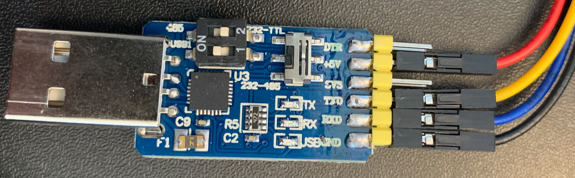
Figure 1. USB to serial converter used to program the Nextion display.
As shown above, this particular USB to Serial converter, which ships with the Nextion display has three switches. This allows the module to be used to convert USB to other forms of two-wire communication, such as RS-485 and TTL. To successfully connect to the Nextion, the switches on the USB to Serial converter must be toggled to the states shown in Figure 1: Switch 1 on, Switch 2 off, and the third switch directed away from the TTL label.
The table below describes the different variables and software objects used in the Nextion configuration file. Each object belows to the page that it was created on. Global variables can be accessed on any page and local variables can only be accessed on the page that it was defined on.
| Object Name | Type | Scope | Description |
|---|---|---|---|
| page0.va0 | Variable | Global | Stores the current drive mode. Identical to buttonState in Interface.cpp, 1->Direct, 2->Coast, 3->Regen, 4->Boost, 5->Pedal. |
| page0.va1 | Variable | Global | Vehicle speed, in miles per hour, integer form. This value is used by the Plot page to chart speed vs. time. |
| page0.tm0 | Timer | Local | This timer object has a period of 50 ms. Every 50 ms, the green bars for the speed and accumulator pressure are updated based on the current speed and pressure. |
| page0.n0 | Number | Global | Accumulator pressure, in psi. |
| page0.x0 | Float | Global | Vehicle speed, in miles per hour, float form. This value is only used on the home page to add resolution to the speed measurement. |
| page4.tm0 | Timer | Local | This timer object has a period of 50 ms. It is used to update the waveform. Every 50 ms, the plot is updated with the current vehicle speed and the distance traveled is calculated. |
| page4.va0 | Variable | Local | Stores the current vehicle speed in integer form, pulled from the value of page0.va1. This value must be reassigned to a local variable in order to correctly calculate distance traveled. |
| page4.va1 | Variable | Local | Stores the intermediary calculation for change in distance traveled (see bullet point at the bottom of the page). |
| page4.x0 | Float | Global | Distance traveled, in feet. As discussed in task_HALL1(), this value is displayed to four decimal places solely as a result of calculating distance traveled, as the Nextion is incapable of floating point math. |
There are six pages in the Nextion interface (zero-indexed). The page IDs and descriptions are summarized in the table below.
| Page ID | Description |
|---|---|
| page0 | Home screen and dashboard. |
| page1 | Help screen. It shows a QR code that directs to this wiki. |
| page2 | Drive mode switch board. Shows five virtual switches that change the vehicle's drive mode. |
| page3 | Hydraulic circuit. Shows the manifold schematic and indicates which valves are currently energized. |
| page4 | Plot. Shows a plot of vehicle speed vs. time, and displays distance traveled (only while viewing the Plot page). |
| page5 | Animation. Shows a 3D orbit of the hydraulic vehicle. |
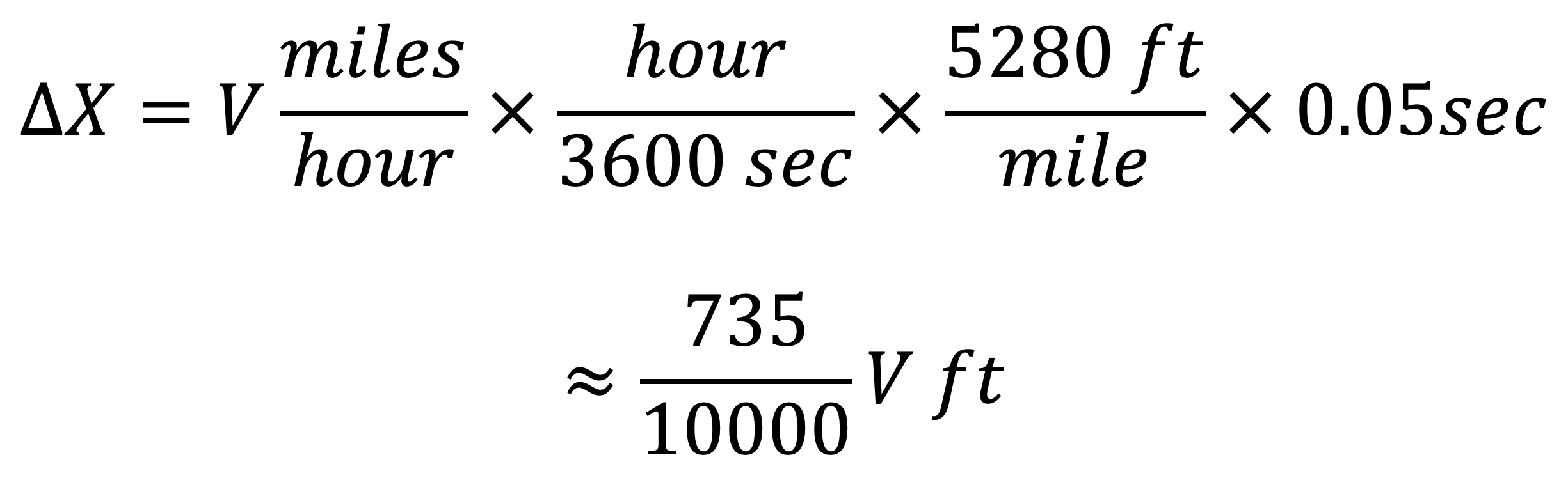
page4.va0 is multiplied by 735 to calculate change in distance traveled x10^4. In order to return this variable to the correct magnitude, we shift the decimal point in the simulated floating point number, page4.x0, by 4, which appears to decrease its magnitude by 10000.