|
Cal Poly NFPA Vehicle Challenge
Soulenoid Cycle, 2021.
Support documentation for various mechatronics components on the vehicle.
|


|
|
Cal Poly NFPA Vehicle Challenge
Soulenoid Cycle, 2021.
Support documentation for various mechatronics components on the vehicle.
|
|
#include "Interface.h"#include "taskshare.h"#include "taskqueue.h"#include "EasyNextionLibrary.h"#include "STM32FreeRTOS.h"#include "SPI.h"#include "mcp2515.h"Macros | |
| #define | coastButton PA15 |
| Macro definition for GPIO pin attached to coast button. | |
| #define | directButton PB3 |
| Macro definition for GPIO pin attached to direct drive button. | |
| #define | boostButton PB4 |
| Macro definition for GPIO pin attached to boost mode button. | |
| #define | regenButton PB5 |
| Macro definition for GPIO pin attached to regenerative braking button. | |
| #define | HALL1 PB12 |
| Macro definition for GPIO pin attached to hall effect sensor. | |
| #define | CS PA4 |
| Macro definition for GPIO pin atached to the MCP2515 chip select. | |
Functions | |
| bool | debounce (uint8_t buttonPin, uint8_t length, bool sign=true) |
| Function to debounce a signal from a GPIO pin. More... | |
| void | ISRcoast () |
| Interrupt service routine for the coast mode button. More... | |
| void | ISRdirect () |
| Interrupt service routine for the direct drive button. More... | |
| void | ISRboost () |
| Interrupt service routine for the boost mode button. More... | |
| void | ISRregen () |
| Interrupt service routine for the regen mode button. More... | |
| void | CAN_sendPress (MCP2515 &node) |
| Function to transmit the current button state to the PLC. More... | |
| int32_t | CAN_readPressure (MCP2515 &node) |
| Function to read the accumulator pressure from the PLC. More... | |
| int32_t | calculatePressure (int32_t sensorReading) |
| Function that calculates a pressure, in psi, based on a raw sensor reading. More... | |
| void | updateDriveMode (EasyNex &display) |
| Function to update the drive mode on the Nextion. More... | |
| void | task_display (void *p_params) |
| Task which interacts with the Nextion display. More... | |
| void | task_CAN (void *p_params) |
| Task which interacts with the CAN bus. More... | |
| void | task_HALL1 (void *p_params) |
| Task which reads a hall effect sensor. More... | |
Variables | |
| uint8_t | buttonState = 1 |
| This variable keeps track of which drive mode the vehicle is in. This value is when a button is pressed. | |
| uint8_t | previousButtonState_DSP = 255 |
| This variable is changed by the display task, and keeps track of when the drive mode text on the Nextion display needs to be updated. | |
| uint8_t | previousButtonState_CAN = 255 |
| This variable is changed by the CAN task, and keeps track of when the controller needs to push an update to the PLC. | |
| Share< int32_t > | accumulatorPressure |
| Inter-task variable for storing accumulator pressure values. More... | |
| Share< int32_t > | bikeSpeed |
| Inter-task variable for storing bike speed values. More... | |
| Share< int32_t > | floatSpeed |
| Inter-task variable for storing "float" speed values. More... | |
| Share< bool > | CANconnected |
| Share that stores status of CAN connection. More... | |
This file contains the function files for the RTOS tasks used with the interface controller. It manages three tasks: display, CAN, and hall effect. In the display task, the controller interfaces with a Nextion display using the EasyNextionLibrary header file. The controller communicates with the Nextion using UART. In the CAN task, the controller interfaces with an MCP2515 CAN controller using SPI, which outputs a CAN signal to the CAN bus. In the hall effect task, the controller reads a GPIO pin using a polling method.
As discussed in the section, Software Design, the task with the highest priority is task_HALL1(), which must quickly poll the hall effect sensor to measure the speed of the vehicle. A high-level task diagram is shown in Figure 1.
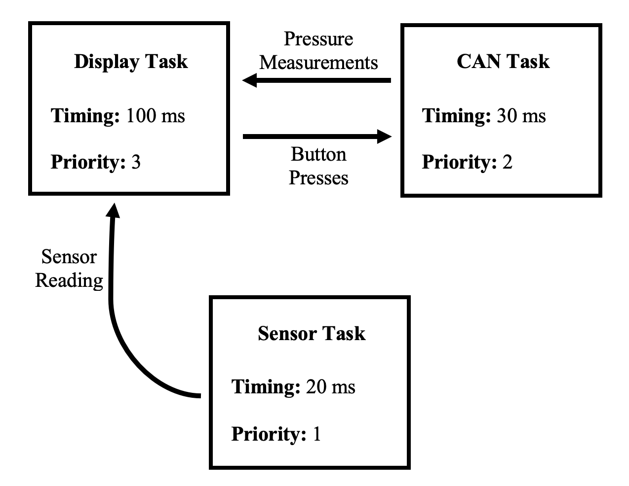
Figure 1. Inter-controller system boundary diagram.
The sensor task, task_HALL1() operates in a simple Finite State Machine (FSM) that switches states based on the high/low status of the hall effect signal. An FSM diagram is shown in the figure below.
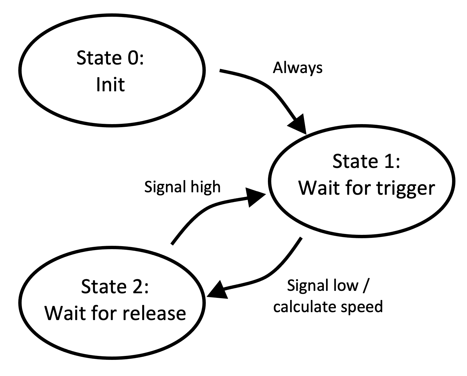
Figure 2. FSM diagram for task_HALL1().
In State 1, the task continuously waits for a hall effect trigger. Since the sensor is active-low, the task uses the function debounce() to identify when the signal transitions from high to low. When this change is identified, the task calculates the speed of the vehicle and stores it in two inter-task variables: bikeSpeed and floatSpeed. See variable descriptions for more information. After the speed is calculated, the task transitions to State 2 to wait until the signal transitions back to high. When the signal returns from low to high, the task transitions back to State 1 to wait for the next pulse.
| int32_t calculatePressure | ( | int32_t | sensorReading | ) |
Function that calculates a pressure, in psi, based on a raw sensor reading.
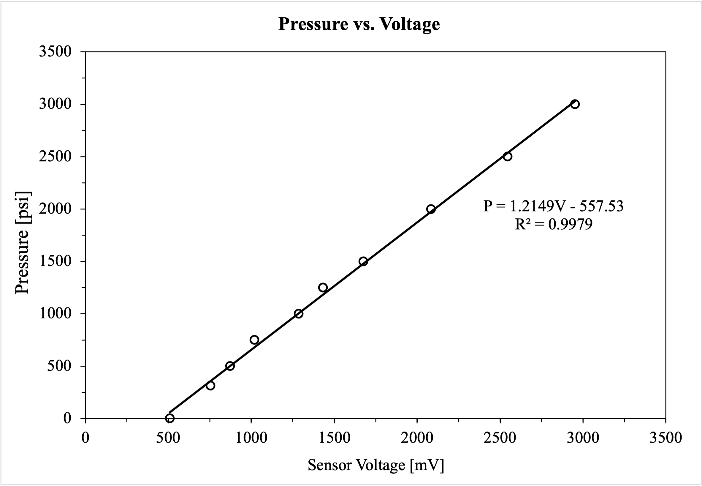
The pressure transducer that is connected to the ECDR 0506-A is configured to output an analog voltage, ranging from 0.5 - 4.5 Vdc. When the controller receives input from this sensor, it interprets the sensor's reading as an integer ranging from 0 - 5000, which represents 0 - 5 Volts. Therefore, the output of CAN_readPressure() will always be an integer ranging from 500 - 4500. When the pressure outputs its maximum voltage, which is 4.5 Volts, it reads its maximum pressure of 5000 psi. When it outputs its minimum voltage, which is 0.5 Volts, it reads its minimum pressure, which is 0 psi.
The sensor was calibrated by incrementally charging the accumulator in Regenerative Braking mode. The raw sensor voltage was recorded along with the accumulator pressure. The accumulator pressure was read from an Ashcroft analog pressure gauge, which carries an accuracy of +/- 1.5%. In other words, at 3000 psi, this gauge is accurate to +/- 45 psi. A linear curve fit was applied to the data to determine a relationship between the accumulator pressure and sensor voltage.
After applying an experimentally determined curve fit to convert the raw sensor reading into a pressure measurement, this function saturates the calculation between 0 and 5000 psi. A plot of the pressure transducer calibration curve is shown in the graph below. Given the accuracy of the analog pressure gauge, the pressure transducer can reasonably measure the accumulator pressure to an accuracy of +/- 50 psi.
The pressure transducer is installed in the hydraulic manifold. Its model is an Ashcroft G2 pressure transmitter. Its datasheet and wiring details are available at this link.
| sensorReading | The output of CAN_readPressure(). An integer between 0 and 5000. |
| int32_t CAN_readPressure | ( | MCP2515 & | node | ) |
Function to read the accumulator pressure from the PLC.
This function reads the CAN bus for the accumulator pressure. The PLC transmits a pressure reading in a 2 byte message with ID 0x181, another arbitrary hex number. The message needs to be 2 bytes long because the accumulator pressure can be up to 3000 psi, which requires 2 bytes. To retrieve the measurement, we need to read each byte, one at a time. The PLC sends the low byte first, and then the second. After we read both bytes of data, we concatenate them into a single number by left-shifting the high byte by 8, and adding it to the low byte. The function returns a 32-bit integer for printing to the Nextion.
| node | The MCP2515 controller that we are interfacing with. |
| void CAN_sendPress | ( | MCP2515 & | node | ) |
Function to transmit the current button state to the PLC.
This function sends a CAN message to the CAN bus based on the current button state. This function only transmits a message if a button was recently pressed. To do this, we use the global variable previousButtonState_CAN, which changes only when buttonState changes. This way, we only send one transmission to the CAN bus whenever a button is pressed, instead of continuously. To sent the message, we construct a CAN message that is only one byte long, with the ID of 0x181, an arbitrary hex number. On the other end, the PLC will first read the ID of the message, and then interpret its data.
| node | The MCP2515 controller that we are interfacing with. |
| bool debounce | ( | uint8_t | buttonPin, |
| uint8_t | length, | ||
| bool | sign = true |
||
| ) |
Function to debounce a signal from a GPIO pin.
This function reads the value from a GPIO pin for a user-specified duration to prevent signal noise. When a drive mode button is pressed, we need to ensure that the rider is pressing a button intentionally, instead of an accidental press or noise from vibration. This function returns true if the function takes enough readings to conclude that a button has been pressed.
| buttonPin | The GPIO pin to read. |
| length | How many readings to take to debounce the signal. |
| sign | Which signal to look for: active-high or active-low. This parameter is TRUE by default, which debounces an active-high signal. If FALSE is passed here, then this method will debounce an active-low signal. |
| void ISRboost | ( | ) |
Interrupt service routine for the boost mode button.
This function is triggered by the rising edge of the signal from the boost button GPIO pin. First, it debounces the signal to make sure that the button was actually pressed, then it sets buttonState accordingly.
| void ISRcoast | ( | ) |
Interrupt service routine for the coast mode button.
This function is triggered by the rising edge of the signal from the coast button GPIO pin. First, it debounces the signal to make sure that the button was actually pressed, then it sets buttonState accordingly.
| void ISRdirect | ( | ) |
Interrupt service routine for the direct drive button.
This function is triggered by the rising edge of the signal from the direct drive button GPIO pin. First, it debounces the signal to make sure that the button was actually pressed, then it sets buttonState accordingly.
| void ISRregen | ( | ) |
Interrupt service routine for the regen mode button.
This function is triggered by the rising edge of the signal from the regen button GPIO pin. First, it debounces the signal to make sure that the button was actually pressed, then it sets buttonState accordingly.
| void task_CAN | ( | void * | p_params | ) |
Task which interacts with the CAN bus.
This task sends the current user-chosen drive mode to the PLC and reads the accumulator pressure, using the CAN bus. We interface with the CAN bus using an MCP2515 controller. On the custom PCB, the MCP2515 controller uses an 8 MHz crystal to clock the CAN bitrate. However, the mcp2515.cpp and mcp2515.h files clock the bitrate using a 16 MHz crystal. This parameter was altered in those files to set the correct bitrate.
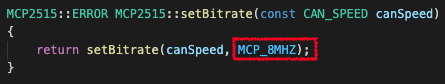
The image above captures the function, setBitrate(), which is part of the MCP2515 library written by GitHub user autowp. The second argument provided to the function represents the type of oscillator used with the MCP2515 integrated-circuit. By default, this value is 16 MHz. However, the PCB designed for this project uses an 8 MHz crystal instead of a 16 MHz one. To establish the correct communication speed on the CAN bus, this parameter must be changed to MCP_8MHZ, as outlined in red in the image above.
| p_params | A pointer to function parameters which we don't use. |
| void task_display | ( | void * | p_params | ) |
Task which interacts with the Nextion display.
This task updates various data on the Nextion, which includes the accumulator pressure and the speed of the vehicle.
| p_params | A pointer to function parameters which we don't use. |
| void task_HALL1 | ( | void * | p_params | ) |
Task which reads a hall effect sensor.
This task polls the GPIO pin for the hall effect sensor. Whenever the triggers low, the task retains the elapsed time, in milliseconds, between pulses. We use the circumference of the wheel to calculate the distance traveled between pulses, and then divide by the time between pulses to calculate speed, which is subsequently converted to miles per hour.
| p_params | A pointer to function parameters which we don't use. |
| void updateDriveMode | ( | EasyNex & | display | ) |
Function to update the drive mode on the Nextion.
This function updates the drive mode on the Nextion display. The user can change the drive mode in two ways: by pressing one of the four buttons, or pressing one of five virtual switches on the touch screen (the fifth button is for pedal charge mode). This function first checks if the user has toggled a switch on the screen by checking a flag in the Nextion software: page2.va1.val. va1 is a boolean flag in the Nextion software that belongs to Page 2 (the switch board page). This function checks its value by reading the variable's attribute: val.
| display | The Nextion display that we are interfacing with. |
| Share<int32_t> accumulatorPressure |
Inter-task variable for storing accumulator pressure values.
Storing these values in a Share makes up for any mismatch in transmission frequencies between the PLC and this controller.
| Share<int32_t> bikeSpeed |
Inter-task variable for storing bike speed values.
Storing these values in a Share makes up for any mismatch in transmission frequencies between the display and hall effect tasks.
| Share<bool> CANconnected |
Share that stores status of CAN connection.
A value of TRUE means that a CAN connection is established, and a value of FALSE means that an error has occured.
| Share<int32_t> floatSpeed |
Inter-task variable for storing "float" speed values.
The Nextion display is incapable of working with floating-point numbers. Instead, Nextion Editor has a way of "faking" floating point numbers by splicing an integer with an artifical decimal point, and then shifting it around to simulate a decimal number. Therefore, to display a the vehicle speed in the format, XX.X, we can multiply the calculated speed by 10, and then the Nextion will shift the decimal place left by 1. For example, if task_HALL1() were to calculate a speed of 10.52 mph, the task will first multiply by 10 and then round to the nearest integer, which will equal 105. Then, task_display() will send the number 105 to the Nextion. The Nextion's software will store the number 105 in its simulated floating point number variable, with a decimal point inserted 1 digit to the left. Thus, the screen will display: 10.5.