|
Cal Poly NFPA Vehicle Challenge
Soulenoid Cycle, 2021.
Support documentation for various mechatronics components on the vehicle.
|


|
|
Cal Poly NFPA Vehicle Challenge
Soulenoid Cycle, 2021.
Support documentation for various mechatronics components on the vehicle.
|
|
Welcome to the official support documentation for Cal Poly's NFPA Fluid Powered Vehicle Challenge team! On this wiki, you will find references and files for various elements of the vehicle's mechatronics system.
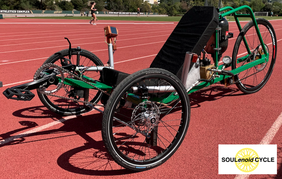
This report discusses the design and prototyping of a custom CAN node user interface for the electronic control system on a hydraulically-powered vehicle. The vehicle’s hydraulic circuit consists of five solenoid valves, which are actuated in combinations to achieve different vehicle behaviors. A rider applies human power input to the vehicle using a standard bicycle crankset. The crankset’s shaft is coupled with a hydraulic pump that draws fluid from a pressure-neutral reservoir. The pump circulates fluid through a bi-directional hydraulic motor that propels the vehicle. The rider can also release fluid from a pressurized accumulator that applies a “boost” to the vehicle’s speed.
Existing hydraulic and electronic components are provided by HydraForce, Inc. Sourcing all components from a single company lends itself to a well-integrated mechatronics system. However, its functionality is not expandable beyond fluid power control. The system’s industrial Programmable Logic Controller (PLC) only has one inter-controller communication peripheral: CAN bus, and cannot be programmed using open-source languages, such as C++ or Python. This project offers a low-cost, open-source user interface for this mechatronics system using CAN bus.
The existing mechatronics system uses a HydraForce ECDR 0506-A electronic valve driver. The vehicle’s operator provides input to the system using three push-buttons, which each represent a unique combination of valve actuations. The ECDR 0506-A, shown in Figure 1, has six inputs, which can be configured to receive an analog voltage or current. With three inputs used for push-buttons, the controller is only capable of reading up to three pressure sensors. An additional CAN node that could relay button presses to the central controller would allow it to interface with additional sensors and inputs.
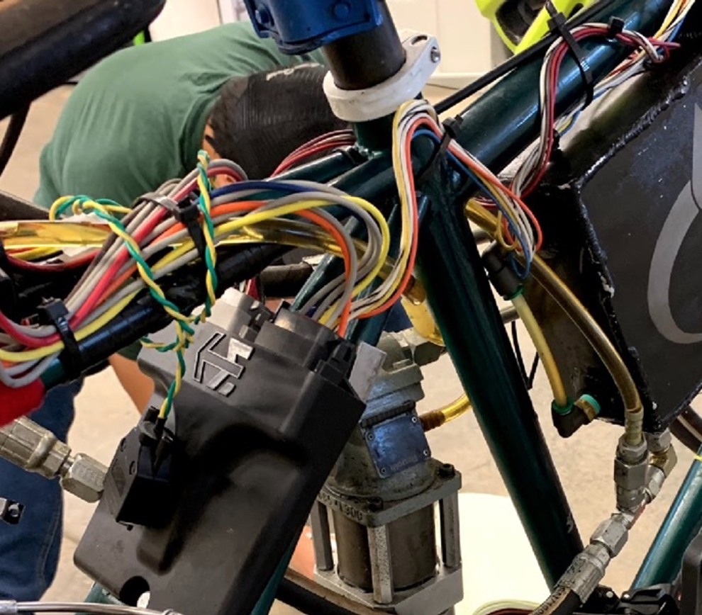
Figure 1. Existing mechatronics system with the ECDR 0506-A valve driver.
A screen capture of part of the programming for the PLC is shown in Figure 2. The software used for this controller is HF Impulse, which is a tool designed by HydraForce to program their controllers.
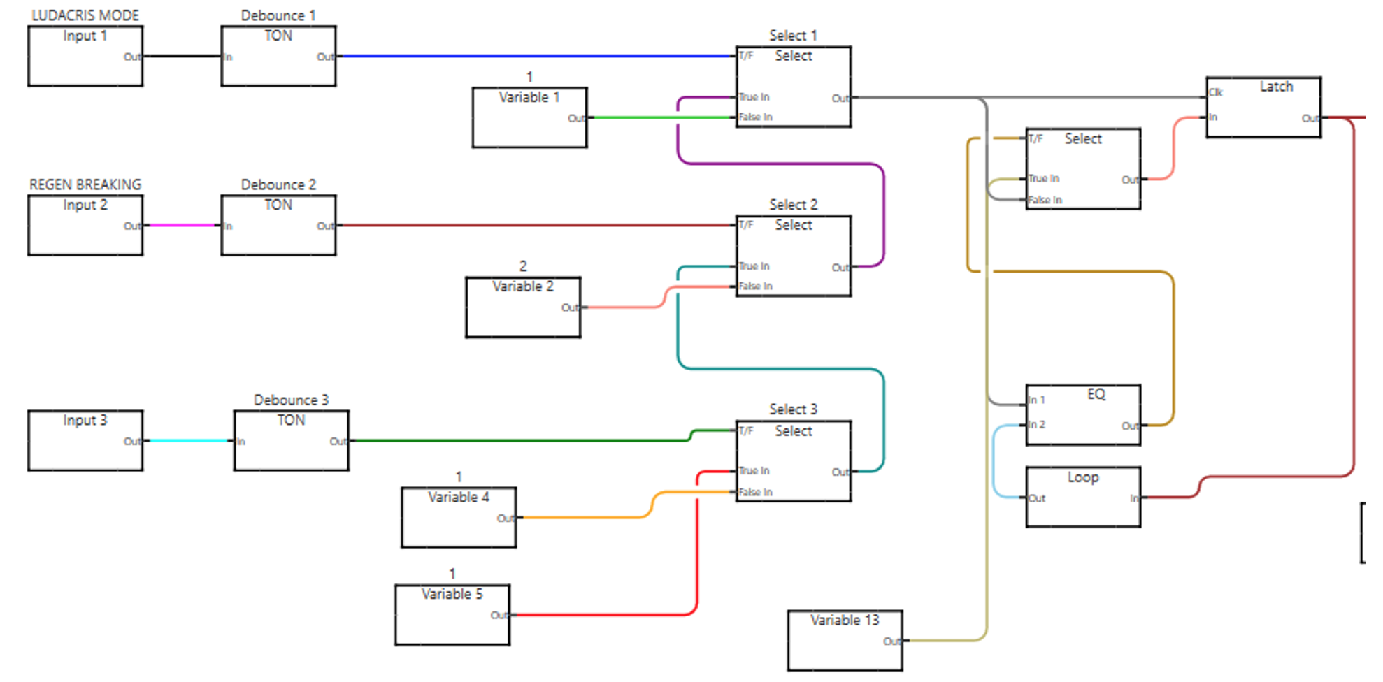
Figure 2. Screen capture of block programming for the ECDR 0506-A.
The goal of this project is to provide a user interface that acquires and displays relevant information about the hydraulic vehicle. The user must be able to read the stored accumulator pressure and the speed of the vehicle. The user should also be able to provide input to the mechatronics system using four push buttons; each button activates a unique combination of solenoid valves.
The custom solution must be more cost-effective and space-efficient than existing solutions. The interface should communicate with the existing ECDR 0506-A valve driver on a CAN bus using J1939 or CANopen protocols. Finally, the system must be able to draw power from an existing 14.8V lithium polymer battery.
Two existing solutions were considered: an OPUS A3F Wachendorff Display Unit, and a SparkFun Arduino CAN shield. The OPUS display unit is a standalone controller that can communicate with other controllers over a CAN bus. Shown in Figure 3, the display has eight configurable button inputs, a pressable rotary knob, and three additional buttons for navigating an interface. It has a 4.3 inch LCD and touchscreen and has a standard DB-9 connector that can be plugged directly into the ECDR 0506-A.
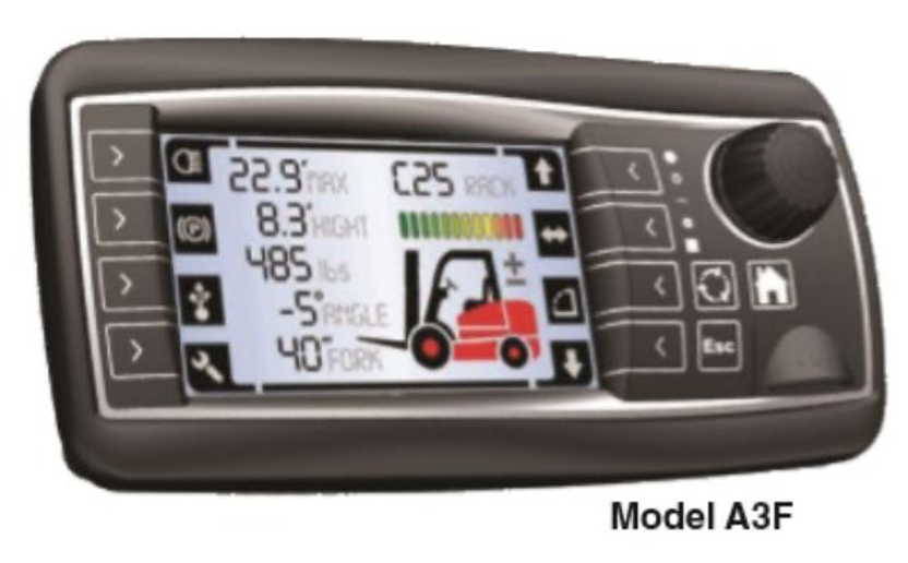
Figure 3. OPUS A3F Wachendorff Display Unit.
The SparkFun CAN shield is designed to add a CAN communication ability to an Arduino Uno. Shown in Figure 4, it fits over the footprint of an Arduino Uno, and contains an MCP2515 CAN controller and MCP2551 CAN transceiver circuit. Like the OPUS A3F, it carries a standard DB-9 connector that can be plugged directly into the ECDR 0506-A. The breakout module also has a micro-SD card port, a joystick, and an additional port to connect to a SparkFun GPS breakout module.
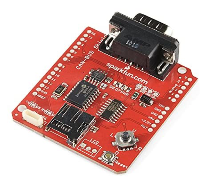
Figure 4. SparkFun CAN bus shield for Arduino Uno.
This product’s main advantage is that SparkFun has already written Arduino code for interfacing with it. SparkFun provides clear and open-source documentation that allows for quick software debugging. However, this product limits the system’s microcontroller to an Arduino Uno’s ATmega328. Discussed further in Hardware Design, the Arduino Uno may be insufficient for navigating a complex user interface with a Real Time Operating System (RTOS).
This section describes the selection process for the CAN node’s microcontroller and its other hardware components. The Arduino framework in C++ was chosen as this project’s software basis. The Arduino framework is well-documented, open-source, and can be used to program a variety of microcontrollers and development boards. Two microcontrollers were considered: an ATmega328, and an STM32. ATmega328, produced by Atmel, is an 8-bit AVR microcontroller commonly found on Arduino modules. STM32 is a family of 32-bit ARM microcontrollers produced by STMicroelectronics. Both ATmega328 and STM32 microcontrollers are available on development boards that carry small footprints. Shown in Figure 5, the Arduino Nano and Blue Pill development boards are both relatively small and carry many useful software and hardware peripherals.
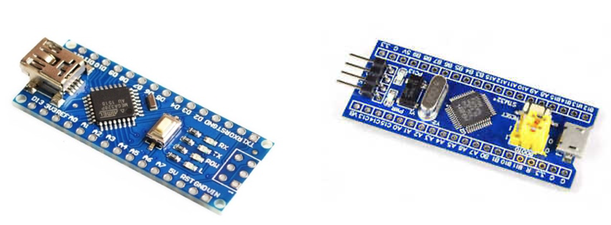
Figure 5. Arduino Nano with ATmega328 (left) and STM32 Blue Pill (right).
The biggest advantage of using an Arduino development board, such as the Arduino Nano of Figure 4, is that its microcontroller is preloaded with the Arduino bootloader. This allows the programmer to upload C++ code directly to the board, which its bootloader uses to program the microcontroller. Conversely, most STM32 development boards require the use of the ST-Link programmer, which is a dedicated controller produced by STMicroelectronics that programs an STM32 in its machine code. Some development boards, such as the Nucleo L476RG, have a built-in ST-Link circuit, however the Blue Pill of Figure 4 carries too small of a footprint to have space for the programmer module.
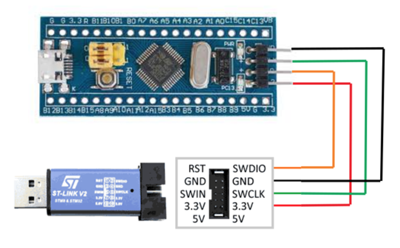
Figure 6. ST-Link programmer used to program the STM32 Blue Pill development board.
The ST-Link programmer is a separate module, shown above in Figure 6, that interfaces with an Integrated Development Environment (IDE) on a PC. While the Arduino Nano can simply be programmed from its USB port, the Blue Pill must be programmed using a serial connection to the ST-Link, as it does not have a bootloader.
Although the Arduino Nano is easier to program, its ATmega328 carries less processing power than the STM32. As an 8-bit microcontroller, it is not ideal for an RTOS and also has fewer communication peripherals. For example, the Arduino Nano only has one USART port, while the Blue Pill’s STM32F103 has three. Furthermore, the Arduino Nano may be clocked up to 16 MHz, while the Blue Pill may be clocked up to 72 MHz. Given the tradeoff of ease of programmability and processing power between the Arduino Nano and Blue Pill development boards, it was prudent to design and prototype with both before choosing a final design.
While the STM32F103 on the Blue Pill has a built-in CAN controller, it cannot be easily accessed with the Arduino framework. To access its CAN peripheral, the microcontroller must be programmed using STM32CubeIDE, which is an IDE produced by STMicroelectronics. To keep the project as open-source as possible, an external CAN controller was chosen, which allows the microcontroller to be programmed in any IDE using the Arduino framework.
The MCP2515 CAN controller was chosen because it is well-documented with many different open-source C++ libraries. In order to communicate with a CAN bus, the MCP2515 receives commands from a microcontroller using a Serial Peripheral Interface (SPI), and then transmits a CAN message using a CAN transceiver. Two transceivers were considered: the MCP2551 and TJA1050. Shown in Figure 7, the two integrated circuits are housed in slightly different packages and have different pinouts.
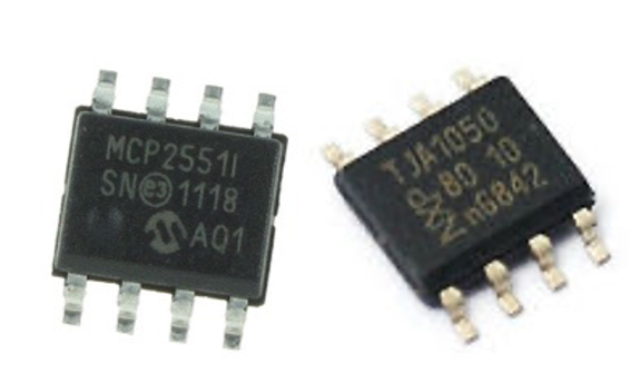
Figure 7. MCP2551 (left) and TJA1050 (right) CAN transceivers.
Aside from their physical differences, the transceivers are functionally the same and are both compatible with the MCP2515 CAN controller. The MCP2551 is used on the SparkFun product of Figure 4, while the TJA1050 is used on a standalone CAN breakout module of Figure 8.
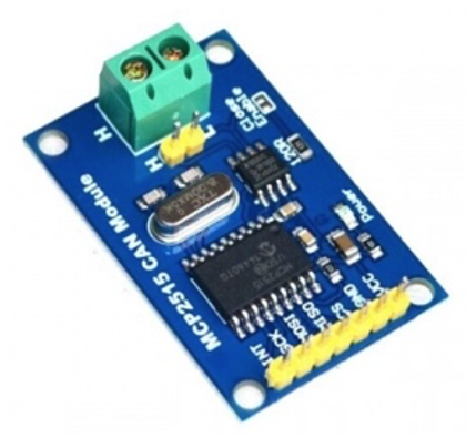
Figure 8. MCP2515 and TJA1050 CAN bus breakout module.
In order to design a graphically-pleasing interface that can display text to the rider in clear, large fonts, two full-color LCD options were explored: A 2.8 inch Adafruit touch screen with the ILI9341 LCD driver, and a 2.8 inch Nextion touch screen. Both options are significantly smaller than the OPUS A3F display unit and can be easily driven by a microcontroller programmed with the Arduino framework. The LCD breakout module of Figure 9 is a low-cost, generic version of an Adafruit Arduino Uno shield. The LCD is driven by the ILI9341 LCD driver, which communicates with a microcontroller over SPI. The breakout module also has a resistive touch screen and SD card slot for displaying bitmap images. This module is easy to use with the Adafruit Graphics Library, which is a suite of Arduino code designed to communicate with several Adafruit display products. Its ease of programmability allows for the quick design of complex shapes and text designs, and the LCD’s resolution and brightness are comparable to that of Nextion displays.
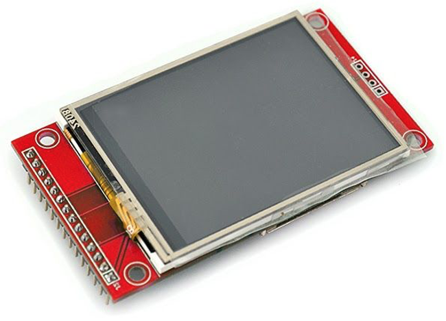
Figure 9. 2.8 inch LCD with ILI9341 driver.
Since this product is nearly three times as cheap as the Nextion display, it was tested first with an Arduino Nano. A skeleton interface was written in C++ and uploaded to an Arduino Nano using the Arduino IDE. The software uses the Adafruit Graphics Library to write data to the screen. The result, shown in Figure 10, was visibly very slow because the Adafruit library uses blocking code to write each shape to the screen. In other words, it was only capable of drawing one independent shape or character at a time without the ability to multitask between communication and pixel-writing.
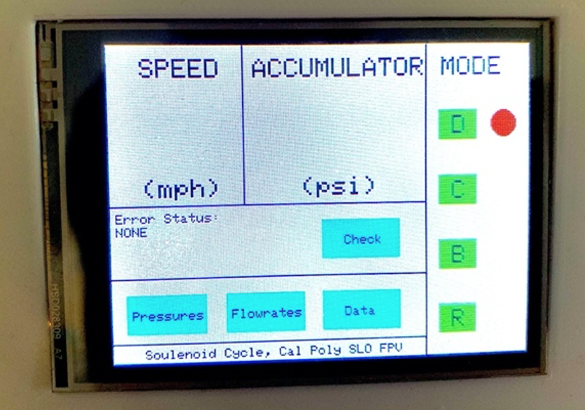
Figure 10. Prototyping with a 2.8 inch LCD with ILI9341 driver and Arduino Nano.
The screen latency was measured as the time elapsed between writing different types of shapes to the screen. Measurements were acquired with the Arduino function, millis(), to calculate a difference in time measurements before and after a shape is written to the screen. The results are quantified in Table 1.
Table 1. Screen latency of Adafruit Graphics Library with ILI9341 LCD.
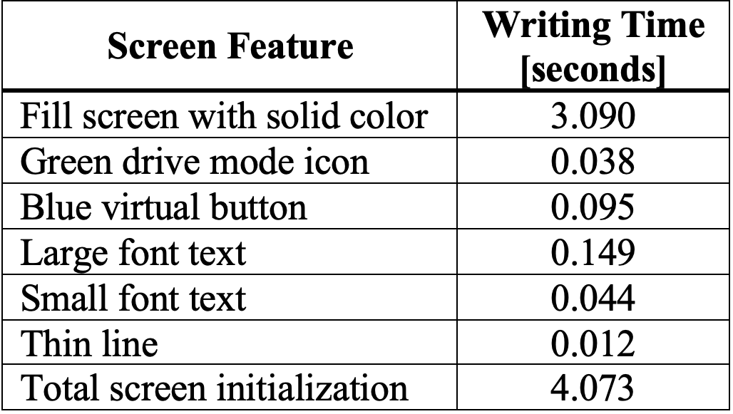
Even if a faster microcontroller were used with this LCD, the latency produced by the Adafruit library would still make it difficult to interact with in a timely manner. Writing custom software to interface with the screen would alleviate its latency, however it would be more efficient to proceed with a different LCD with faster, existing software. The Nextion display differs from a standard LCD driver because it has its own microprocessor with an RTOS. This allows it to multitask independent of the system’s master microcontroller, which results in fast screen refresh rates. A microcontroller communicates with this screen using a UART connection, which is shown in Figure 11 as a 2-wire connection with additional wires for ground and power.
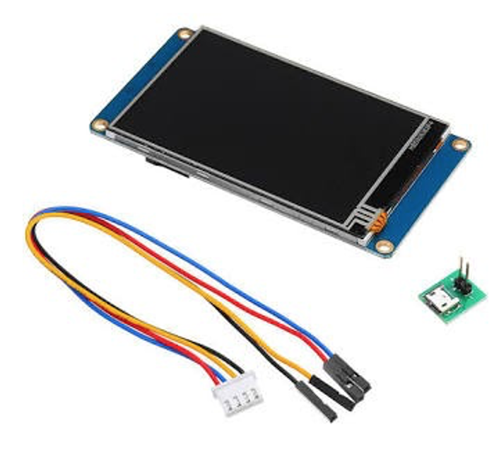
Figure 11. Nextion LCD.
Its functions and screen layout are configured in Nextion Editor, which is a free HMI tool developed by Nextion to program their display modules. The software, shown in Figure 12, allows the programmer to drag-and-drop buttons, images, and text onto the screen. This is a much simpler process than using line code to write each individual pixel or shape. Furthermore, Nextion displays can be easily communicated with using Arduino code. A programmer can use standard serial communication code in either C++ or Python to send commands to the screen.
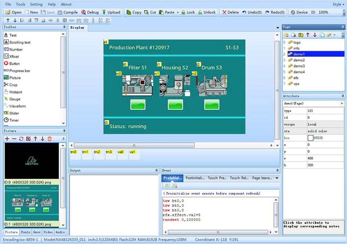
Figure 12. Nextion Editor HMI software.
While its robust configuration tool gives Nextion displays a greater ease of programmability, another required piece of software adds a layer of complexity to the project. The mechatronics system already requires the use of HF Impulse to configure the PLC and a C++ development environment to program the microcontroller. A third programming software would further complicate debugging efforts because it requires the programmer to sift through three different platforms to diagnose problems with a single system.
During prototyping with both Arduino Nano and Blue Pill development boards, two viable Printed Circuit Boards (PCBs) were designed. One PCB includes an Arduino Nano with the MCP2515 CAN controller and MCP2551 transceiver, and the other PCB includes a Blue Pill with the MCP2515 CAN controller and TJA1050 transceiver. After considering both options, the Blue Pill was chosen.
PCB With Arduino Nano
This PCB implements most of the components on the SparkFun CAN shield of Figure 1.3.2. SparkFun publishes open-source schematics of their products. The PCB, shown in Figure 13, contains a CAN communication circuit with the MCP2515 and MCP22551 integrated circuits. In addition, the PCB has a serial port to connect to a Nextion display and JST snap-fit connectors to connect to the push-buttons. The pairs of push-buttons are isolated on independent ground planes, separated by milled slots. This allows both pairs of switches to be detached from the main board and placed in a more convenient location for the vehicle’s rider. To preserve space, this PCB was designed to fit directly beneath a Nextion display, so both components could be stacked on top of each other.
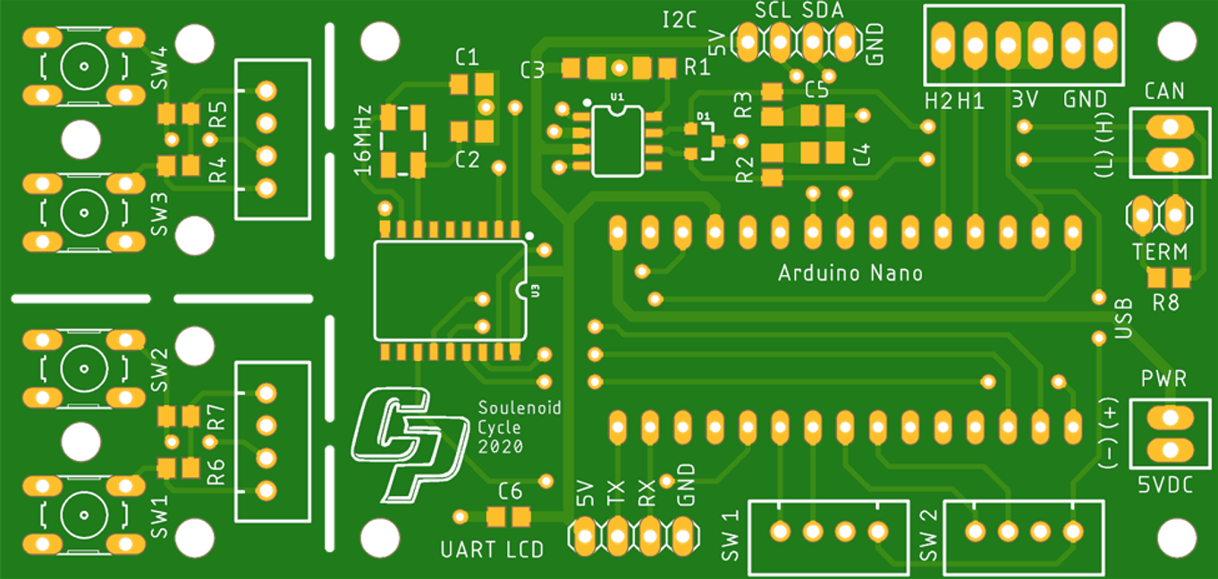
Figure 13. PCB design with Arduino Nano.
PCB With Blue Pill
This PCB uses the CAN circuit on the breakout module in Figure 8, which contains the MCP2515 and TJA1050 integrated circuits. While its overall size is slightly larger than the PCB with the Arduino Nano, it still fits underneath a Nextion display. This PCB, shown in Figure 14, features a similar push-button layout and screw pin terminals for power input and CAN transmission. A polarized capacitor is also placed closed to the power terminals to act as a high frequency noise filter, which reduces noise in the CAN signals.
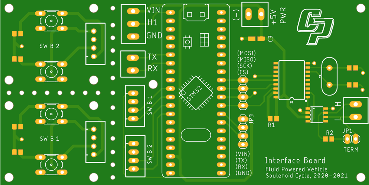
Figure 14. PCB design with STM32 Blue Pill.
Aside from the difference in microcontrollers and CAN transceivers, both circuit boards are functionally identical. After prototyping with the Arduino Nano, this board was ultimately selected because of the STM32’s increased performance abilities. Another advantage of selecting an STM32 over an ATmega328 is its abundance of serial peripherals. Shown in Figure 15, the RX/TX port is configured in software to print debugging information to a serial monitor. If the user encounters a problem with the interface, they can simply connect to the PCB’s serial port to monitor its software and communication.
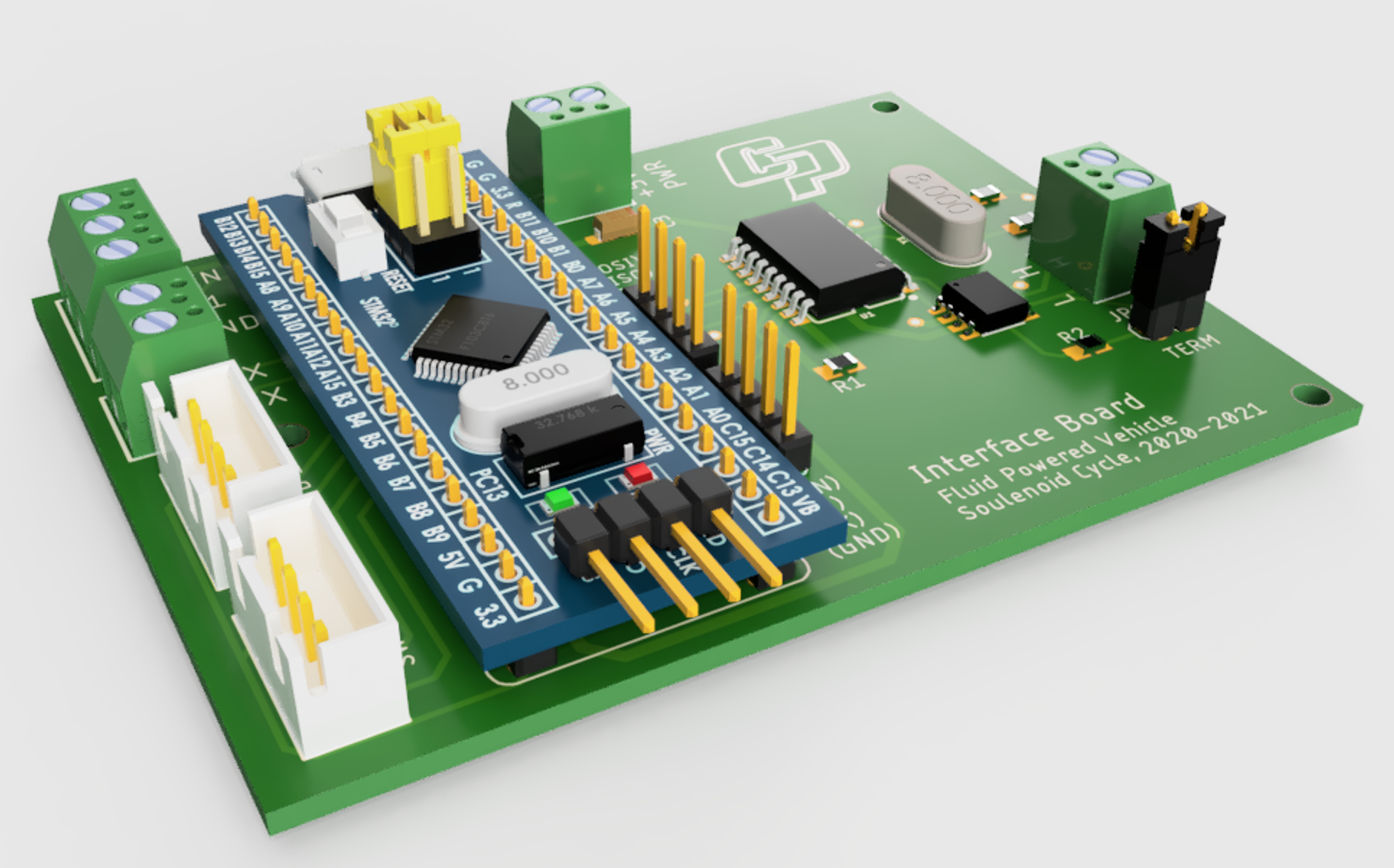
Figure 15. Render of custom circuit board with STM32 Blue Pill.
After designing the circuit board layout in Autodesk Eagle, a 3D model was created in Autodesk Fusion 360 in order to accurately dimension a 3D printed enclosure. For more information about the circuit board design, refer to the Printed Circuit Board Schematic. A render of the circuit board is shown in Figure 15. Populating the circuit board with 3D models, which were obtained from GrabCAD, allowed for more accurate enclosure modeling. The PCB interfaces with its peripherals using a combination of screw pin terminals and JST snap-fit connectors. Screw pin terminals are effective for tightly securing power connections and long-distance signals. JST snap-fit connectors were chosen for the button modules to allow for quick disconnecting.
The ECDR 0506-A is powered by a 14.8V LiPo battery. The ECDR has the ability to output 5V to power an external device, which is enough to power the custom interface node.
This section describes the software design for the STM32 that communicates with the Nextion display and the ECDR 0506-A. The STM32 relays button presses to the ECDR 0506-A over a CAN bus, and receives a pressure measurement from the ECDR 0506-A. The STM32 relays the button presses, pressure measurements, and the vehicle speed to the display. A schematic of inter-controller interactions is shown in Figure 16. The dashed outline represents the system boundary of the STM32’s software. The circled components are passive and are read using hardware interrupts and polling.
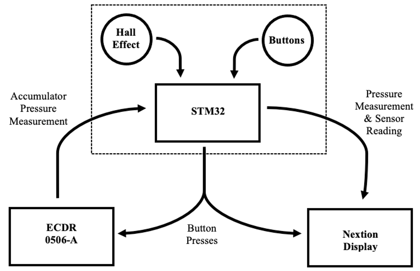
Figure 16. Inter-controller system boundary diagram.
Software for the STM32 uses FreeRTOS, which is an open-source RTOS that works well with STM32 microcontrollers and the Arduino framework. The code is structured into three high-level tasks: display communication, CAN communication, and sensor measurement. In addition, each button is tied to a hardware interrupt.
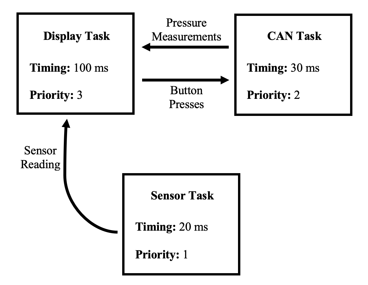
Figure 17. Inter-controller system boundary diagram.
Shown in Figure 17, the display task receives information from the CAN and sensor tasks, which is subsequently relayed to the Nextion display. The display task runs every 15 ms, the CAN task runs every 30 ms, and the sensor task runs every 20 ms. Timing is most critical for the sensor task. The sensor task periodically checks the status of a GPIO pin attached to a hall effect sensor, which is used to measure the speed of a 26-inch bicycle wheel. The task must check the sensor frequently enough such that it doesn’t miss a trigger. The maximum timing period for the sensor task is calculated using the equation,

Where D is the wheel diameter and V is the vehicle’s translational velocity. Using a conservative maximum speed of 45 mph for the human-powered vehicle and a wheel diameter of 26 inches,
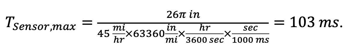
In order to ensure that the sensor task will catch the sensor trigger without fail, it is best practice to poll 5 times faster than the maximum period or settling time. Therefore, a 20 ms timing period was selected.
The STM32 transmits and receives packets of data from the ECDR 0506-A using the MCP2515 library written by GitHub user, autowp. Messages to and from the ECDR 0506-A are transmitted in bytes. Each CAN frame has an 11 bit message ID. The STM32 first identifies the ECDR 0506-A with the message ID, and then constructs and sends a message. The code below sends a button press in 1 byte of data. The function, sendMessage(), transmits the message through the MCP2515 controller.
if (buttonState != previousButtonState_CAN)
{
    struct can_frame canMSG;                              // Create a CAN message structure
    canMSG.can_id = 0x181;                                // COB-ID for transmitting a PDO message
    canMSG.can_dlc = 1;                                   // Define the message length as 1 byte
    if      (buttonState == 1) {canMSG.data[0] = 0x01;}   // If buttonState is 1...      then send a 1
    else if (buttonState == 2) {canMSG.data[0] = 0x02;}   // Else if buttonState is 2... then send a 2
    else if (buttonState == 3) {canMSG.data[0] = 0x03;}   // Else if buttonState is 3... then send a 3
    else if (buttonState == 4) {canMSG.data[0] = 0x04;}   // Else if buttonState is 4... then send a 4
    else if (buttonState == 5) {canMSG.data[0] = 0x05;}   // Else if buttonState is 5... then send a 5
    node.sendMessage(&canMSG);                            // Send the message
    previousButtonState_CAN = buttonState;                // Reset to prevent continuous transmitting
}
The Nextion display’s RTOS assigns an ID to each item on the screen. A text box may have the ID, t0, and a button may have the ID, b0. Each element on the screen is an instance of a class object: t0 is an instance of the text box class and b0 is an instance of the button class. The STM32 interacts with the display by modifying the attributes of its elements. For example, to change the value of n0 on the screen, the STM32 would send a command like, n0.val = 10. This command modifies the “value” attribute of the number object, which is subsequently updated on the display. Communication between the STM32 and the Nextion display is achieved over a UART connection with the Easy Nextion Library, written by GitHub user, Seithan. The code below sends two numbers to be printed on the display.
myNextion.writeNum("n0.val",localVar_bikeSpeed);                     //     Write the speed to the display
myNextion.writeNum("n1.val",localVar_accumulatorPressure);           //     Write the pressure to the display
The display’s Graphical User Interface was designed in Nextion Editor. It consists of a home page that displays all relevant data to the user, which includes the speed of the vehicle, and pressure measurements from the ECDR 0506-A. The user can press several buttons on the touch screen that access different pages. Shown in Figure 18, a second pages allows the user to select a drive mode from one of five switches. Since there are only four physical buttons, the Pedal Charge mode is only accessible using the touch screen. The Circuit page displays the hydraulic circuit schematic, which labels the five controllable valves installed on the hydraulic manifold. The dashed outline is the system boundary of the manifold. The pump, accumulator, and reservoir are also shown on the circuit page. Depending on which drive mode is active, the valves on the circuit will turn green when energized. The Plot page charts the vehicle speed against time in a scrolling, fixed-scale format. The distance traveled is calculated by multiplying the velocity by change in time. Shown in the plot, the variable that stores the distance traveled is displayed with a resolution of 4 decimal places. This is solely because the Nextion is incapable of working with floating point numbers, so converting speed from miles per hour to feet per second, and then multiplying by a time interval in milliseconds, requires a tedious process that results in a calculated value that displays to four deimcal places. For more information, refer to Interface.cpp or Nextion Editor. Finally, the Help page displays a QR code that links to this documentation wiki.
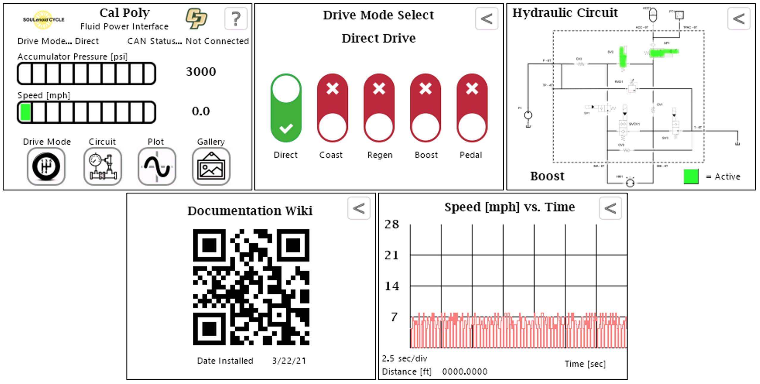
Figure 18. Screen captures of five pages from the interface’s GUI.
The user interface is separated into three components housed in 3D printed enclosures: the display and PCB, and two button modules. All 3D parts were printed with a Bibo 2 Touch 3D printer.
The main interface houses the Nextion display and custom PCB. Shown in Figure 19, the enclosure is hinged to provide access to the circuit board. To connect to the PCB’s screw pin terminals, the user must unhinge the display to expose its circuitry. Hiding the PCB terminals and connections improves its weather resistance.
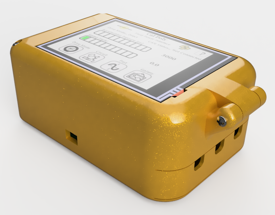
Figure 19. Render of 3D printed interface enclosure.
Narrow, rectangular slots allow for wires to leave the enclosure. A removable cap with three round holes is attached to the bottom of the enclosure with M2 screws. This cap allows for the user to conveniently snap the JST button connections into place without having to unhinge the display. Shown in Figure 20, the enclosure is secured by M2 screws and heat-set brass inserts. The inserts allow for machine screws to be threaded directly into 3D printed parts and are installed with a soldering iron.
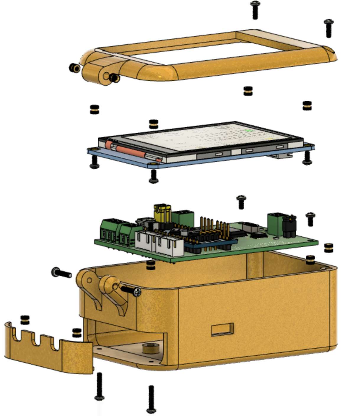
Figure 20. Exploded view of 3D printed interface enclosure.
The button modules are placed in ergonomic locations on the vehicle to allow the operator to easily press a button while driving. Shown in Figure 21, the button enclosure has a single hole for its signal wires to leave. The rest of the enclosure completely hides its circuit board.
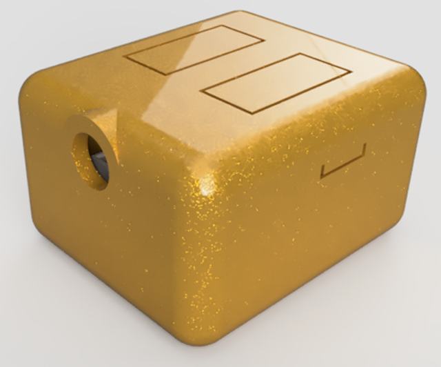
Figure 21. Render of 3D printed button module enclosure.
Like the interface enclosure, the button enclosure is secured by M2 screws and threaded brass inserts. Shown in Figure 22, the rectangular button covers are held captive inside the enclosure by a slot that prevents them from slipping out.
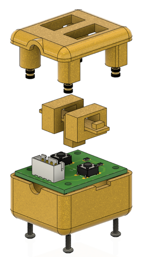
Figure 22. Exploded view of 3D printed button module enclosure.
To mount the screen module to the handlebar, a stand was designed to fit over the top of the handlebar tube. Shown in Figure 23, the stand is angled upwards at 10 degrees to direct the screen toward the rider's eyes. It fits over the 38 mm aluminum tubing and is fixed to the handlebar using a single #6-32 screw. Visible in the wireframe profile, the stand has an internal feature that allows a pair of 18 AWG wires to snake through and reach the screen module. This feature neatly conceals the power lines inside the handlebars. The screen stand also has deep channels to glue strips of velcro. The combination of velcro and the power terminals rigidly fix the screen module to the stand.
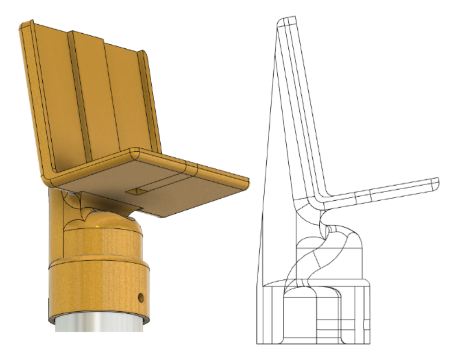
Figure 23. 3D printed screen stand.
This section discusses the manufacturing, assembly, and testing of the CAN node interface. Shown in Figure 24, the PCB works as expected. A Dremel rotary tool with a cutting wheel attachment was used to separate the button modules from the main board, and sand paper was used to clean up its edges. The single mounting hole directly next to the white JST connectors was difficult to access after assembly; in a future iteration, it is recommended to extend the board to provide sufficient space for more mounting holes.
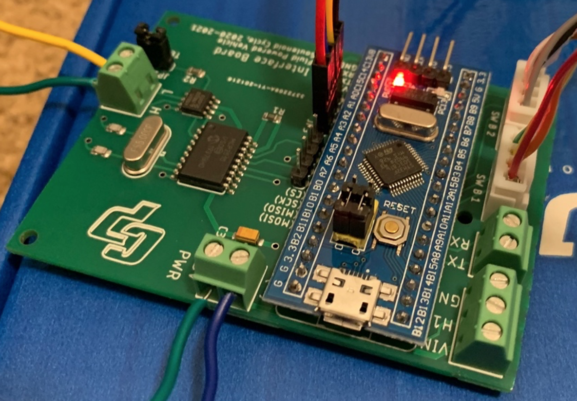
Figure 24. Printed Circuit Board after assembly.
The screw pin terminals effectively secure the CAN and power lines, however it would be more convenient if their terminals were located closer together. This PCB requires wires to leave the board from three of its sides, which makes it more difficult to band wires together in cable strips. The PCB also has a significant amount of free space. Finally, it is recommended to switch to smaller connectors. The screw pin terminals, Dupont connectors, and JST connectors significantly raise the overall height of the PCB assembly, which contribute to the thickness of its enclosure. Connectors that carry smaller footprints would reduce the overall size of the interface module.
The threaded brass inserts most significantly contribute to the success of the enclosures. They tightly secure the PCB and Nextion display to the 3D printed parts. Shown in Figure 25, the parts were printed with PLA in a silk-copper filament, which adds a shiny texture to each enclosure. The buttons are easily pressable, and respond with an audible “click.” For information about the durability of the enclosures, see Design Verification and Testing.
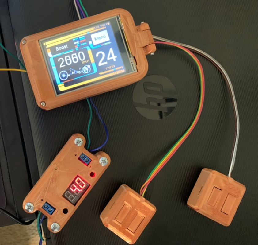
Figure 25. 3D printed enclosures after final assembly (note that the screen shows an outdated interface).
Shown in Figure 26, the JST connectors are easily accessible through the enclosure’s bottom hatch, and allow the cables to rest in the round notches. In addition, the STM32’s programming ports are easily accessible through a narrow slot in the enclosure, which allows it to be programmed without disassembling. Accessing the PCB through a hinge allows the enclosure to remain in one piece, which alleviates the concern of damaging wire connections and losing screws. In order to access the PCB, the user must remove two screws located in the corners of the display, which are visible in Figure 27. In a future design iteration, it is recommended to design snap-fit connections between the enclosure’s top and bottom so the user could unhinge the display without removing any screws.
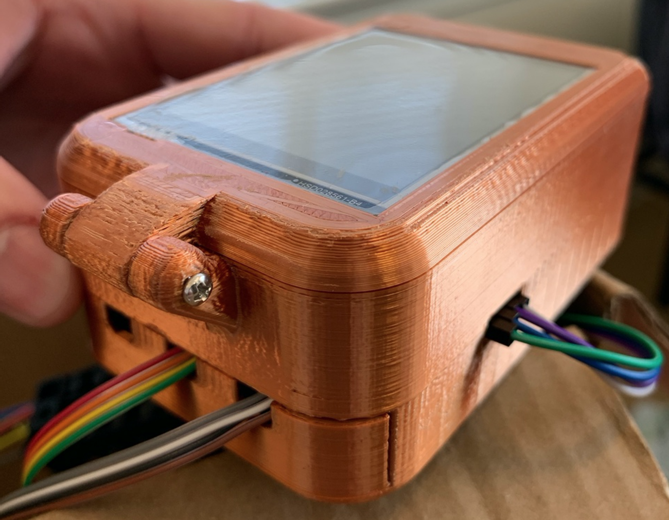
Figure 26. 3D printed display and PCB enclosure.
The enclosures were printed with a layer height of 0.15 mm and a print speed of 50 mm/s. These settings are effective for rapid prototyping, however the increased speed and layer height results in layer imperfections and print defects. Shown in Figure 26, the hinge had to be sanded to remove some defects, which also removed some of the PLA’s shiny finish. Furthermore, these parts were not printed on a high-end 3D printer, which also contributed to their overall quality. It is recommended to print these parts on a precision 3D printer at a decreased speed and layer height to maximize their surface finish and durability.
The interface enclosure is mounted on the right handlebar of the hydraulic vehicle. The CAN and power wires are routed through the aluminum handlebar, and the button and hall effect sensor wiring are routed on the outside of the handlebar. The module is attached to the 3D printed stand with velcro. Its usage and mounting is visible in the video below.
Please see the video below for details regarding the usage of the interface. The video shows each page operating in real time, and demonstrates how to change drive modes and view the hydraulic circuit.
The mounting of the screen and buttons are shown in Figure 27. The location of the power terminals on the PCB ended up being ideally placed for proper concealement on the vehicle. An angled stand was designed with an internal hole that allowed the two power wires to snake through the handlebars. Since the handlebars were welded from two aluminum tubes at a right angle, it was difficult to pull more than a few wires through the handlebars. Thus, the wires for the speed sensor and buttons had to be routed along the outside of the handlbars. In addition, the location of the CAN terminals on the PCB requried another hole in the handlebars, which is also visible in Figure 27. In a future iteration, it is recommended to concentrate all terminals and wire connections in a single location on the PCB. It would significantly improve the aesthetics of the screen mount to construct a single cable ribbon that is completely concelealed within the handlebar. Shown in Figure 27, the buttons are attached to the handlebars with velcro strips, which were suprisingly resilant. The buttons and screen are intended to be as modular to allow the rider to customize their desired layout. The screen module itself, which is shown isolated in Figure 26, is also attached to the screen mount with strips of velcro. For durability, the power supply to the board and the CAN wires should remain thick (18 AWG wire is currently used). However, the wires that only relay 5V signals can be reduced to 24 or 26 AWG to reduce the volume and weight of the wiring.
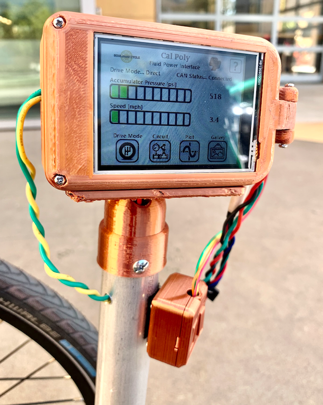
Figure 27. Location of screen module on right handlebar.
An advantage of using a recumbent tricycle frame is the abundance of space for storing electrical components. Shown in Figure 28, the cushioned seat is attached to the frame with velcro strips. Underneath the seat are the ECDR 0506-A and battery, which are therefore more protected from the elements. The ECDR 0506-A is angled toward the manifold, which improved cable management among the valve connections. In order to turn the electronics on, the rider must lift part of the seat and plug the battery in. While this encourages the rider to not leave the vehicle turned on, it would be easier if the battery can be powered on using an easily accessible switch. Also, neither the ECDR 0506-A nor the custom interface are capable of measuring battery level. Each of the five valves requires a current supply of 2 A to full actuate, and the custom interface requires at least 500 mA to function normally. It is recommended to design a power management system that can alert the rider when the battery is unable to supply the current needed to energize the valves and power the screen. This could be accomplished with an additional CAN node that can facilitate the charging of the battery and monitoring its status. Finally, the battery life of the vehicle ranges from 45 minutes to an hour. It is recommended to increase the size of the battery to better accomodate the power requirements of the system.
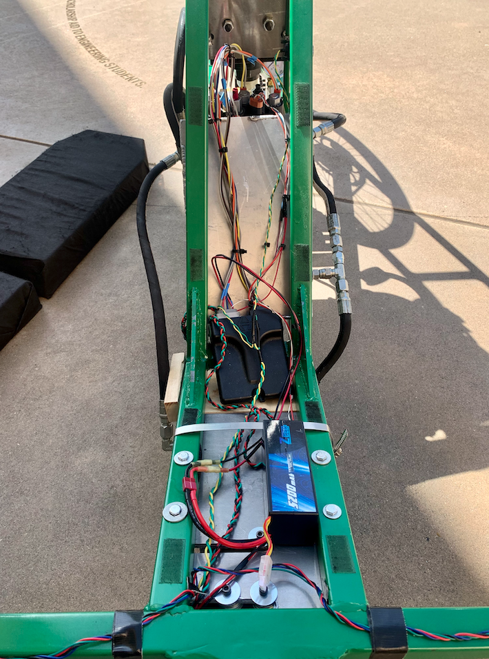
Figure 28. Location of ECDR 0506-A and battery underneath the seat.
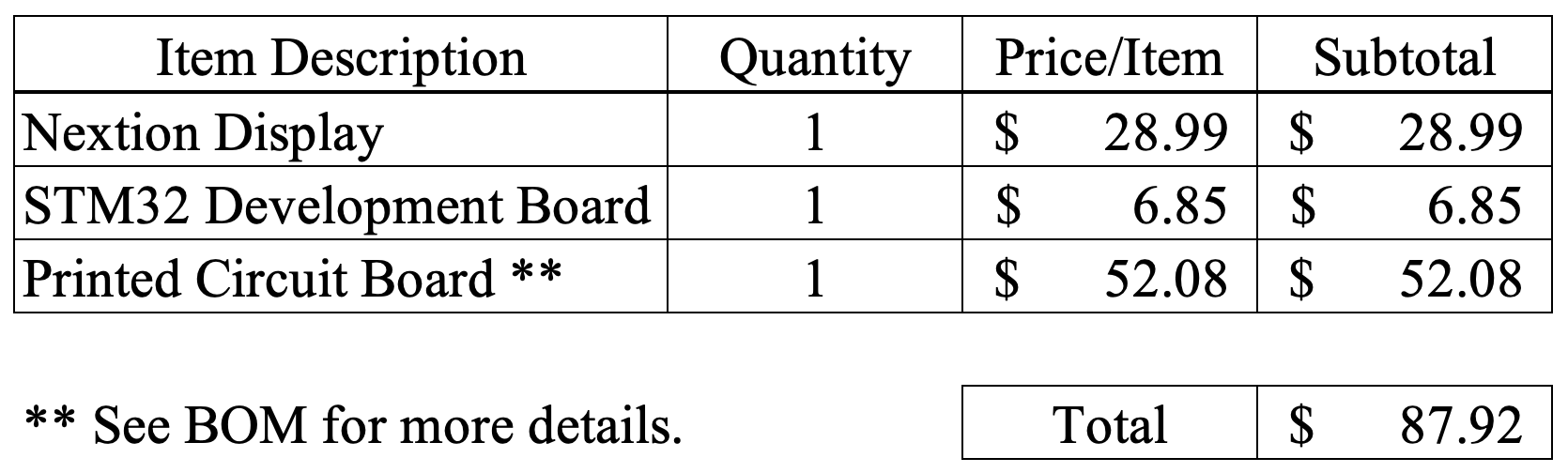
The table below summarizes the total expenses for this project. The JST and Dupont connections, jumper headers, and push buttons were not included as expenses; they were already obtained. Since the enclosures were 3D printed at home, their cost of manufacturing is negligible. It is also notable that the printed circuit boards, which were ordered from JLC PCB, have a minimum order quantity of 5 boards. The $52.08 expense encompasses the total cost of manufacturing 5 circuit boards. In addition, this cost encompasses the surface mount components for two boards to provide a replacement in case one is damaged.
Table 2. Summary of total project expenses.